General Specs:
Class: AB2
Plate voltage: 3.2-4kV
Max Power: 1900W PEP
Bands: 160, 80, 40, 20, 15, 10m
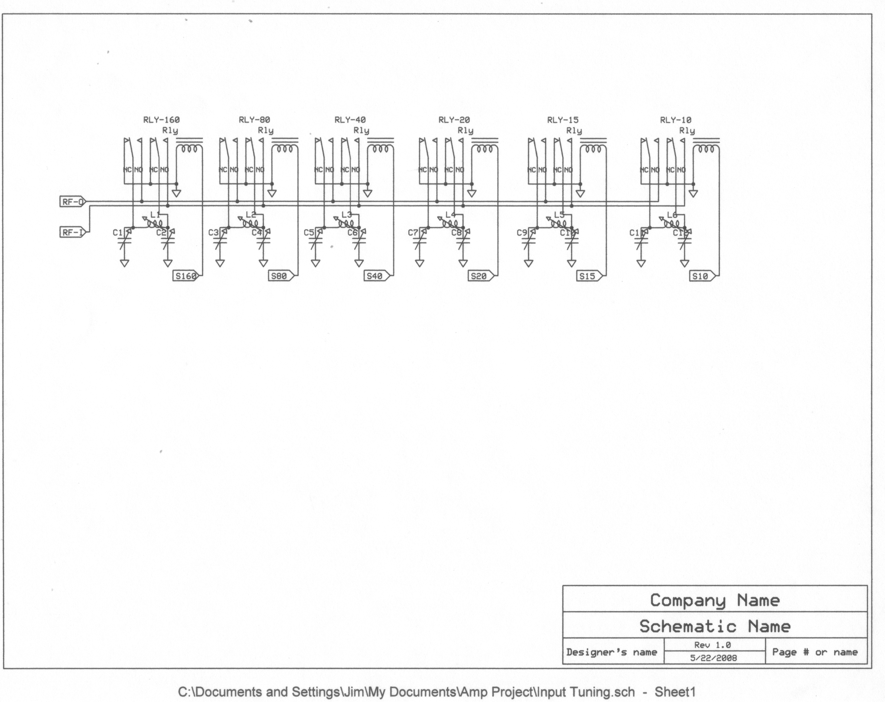
Input-tuned network
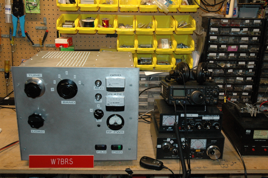
The homebrew linear is finished and is in testing.
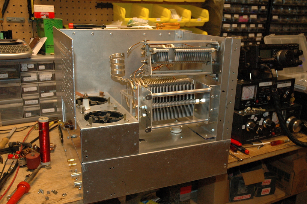
New Bottles with original Tank
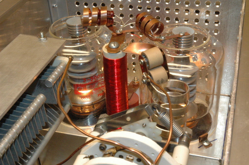
Also ordered, and installed is a new Load capacitor. The new Load cap is 0-1400pF, and a bit larger width-wise so I had to rearrange parts of the tank to accomodate (new bracket and new holes through the front panel).
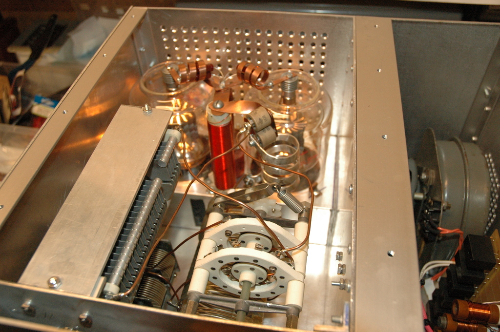
(the Load cap is the big variable capacitor on the bottom. The variable capacitor on the top is the Tune cap and is in two sections. The tail (shorter) section is brought in on 80/160m bands only.)
New Load cap fitted in during the Tank re-work
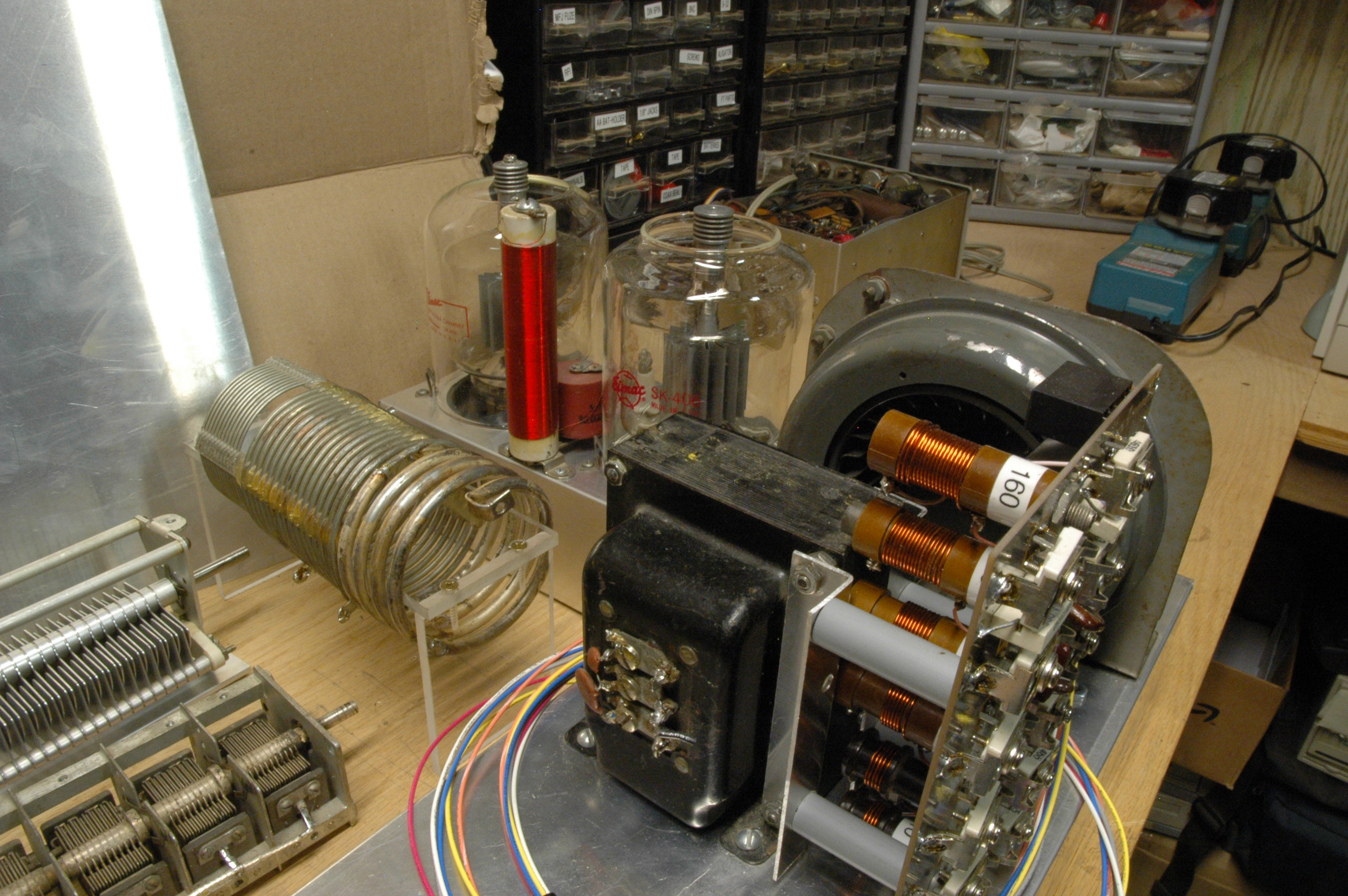
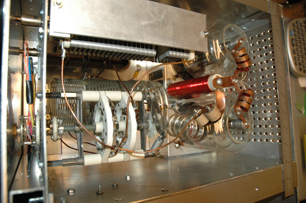
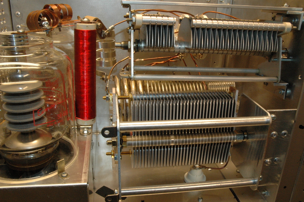
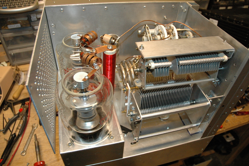
New Tank with new Load cap, and new
parasitic chokes
New Tank with new Load cap, and new parasitic chokes (2nd view)
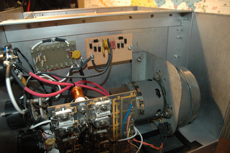
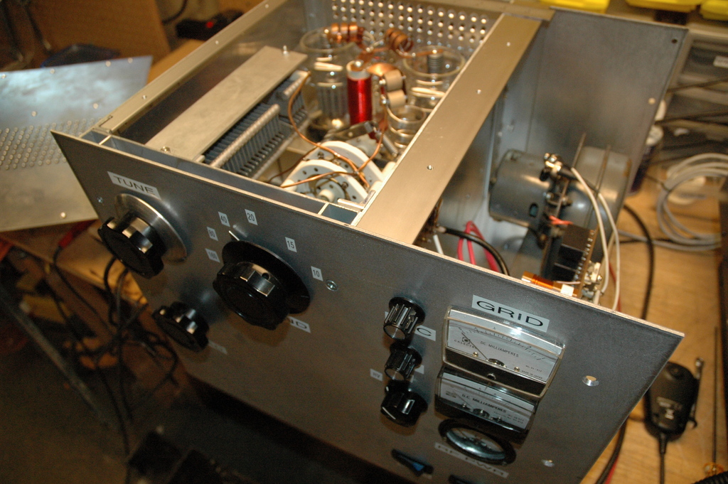
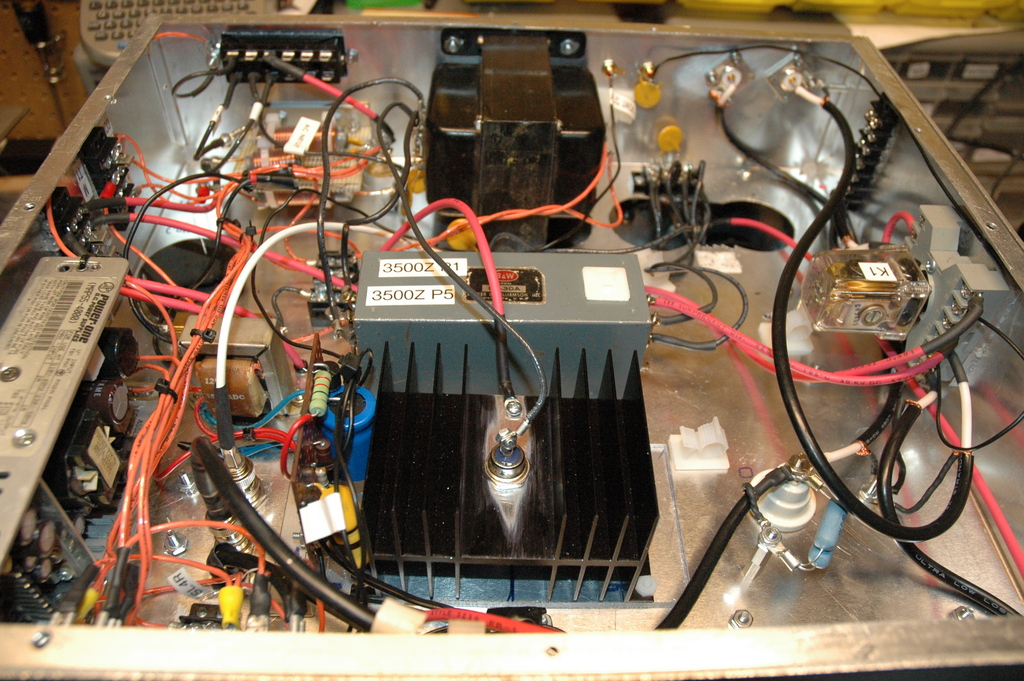
The insides of the amp pizza-box
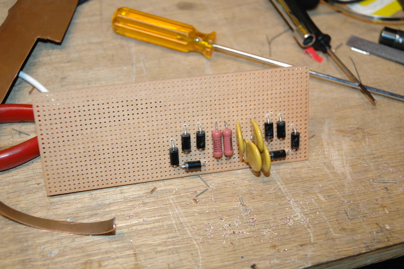
Everything is hand made except where obvious. The input tuning board provides the match on the input side (to pin 1 of the tubes). The input tuning is a pi-network for each band. The slave rotary switch on the bandswitch selects the relay on the input tuning board to bring that band into the circuit. I can bypass the input tuning board easily because I used bulkhead BNC connectors through the chassis next to the board. The RF sampling meter circuit is also fed through a similar jack for keeping that signal clear and isolated as much as possible.
My bias is a 50W 6.8V Zener on a 50W heatsink. I have an option later to add another switch on the front panel to switch the bias for a CW or SSB operation. I am also looking at some other schematics/texts on perhaps making the bias even more 'selectable', but not at the moment.
The main coil is 3" diameter. There's a 1.5" diameter coil on the plate side that is silver plated ribbon. The coil is extended to work 160m.
The Tune cap is augmented for 80 and 160m with additional variable capacitance.
My HV outboard power supply is able to provide either 3.2k or 4kV. It's wired now for 3.2kV.
The HV wires are coarse stranded wire in PVC jacket. OD is 0.140" and can handle an 20kV.
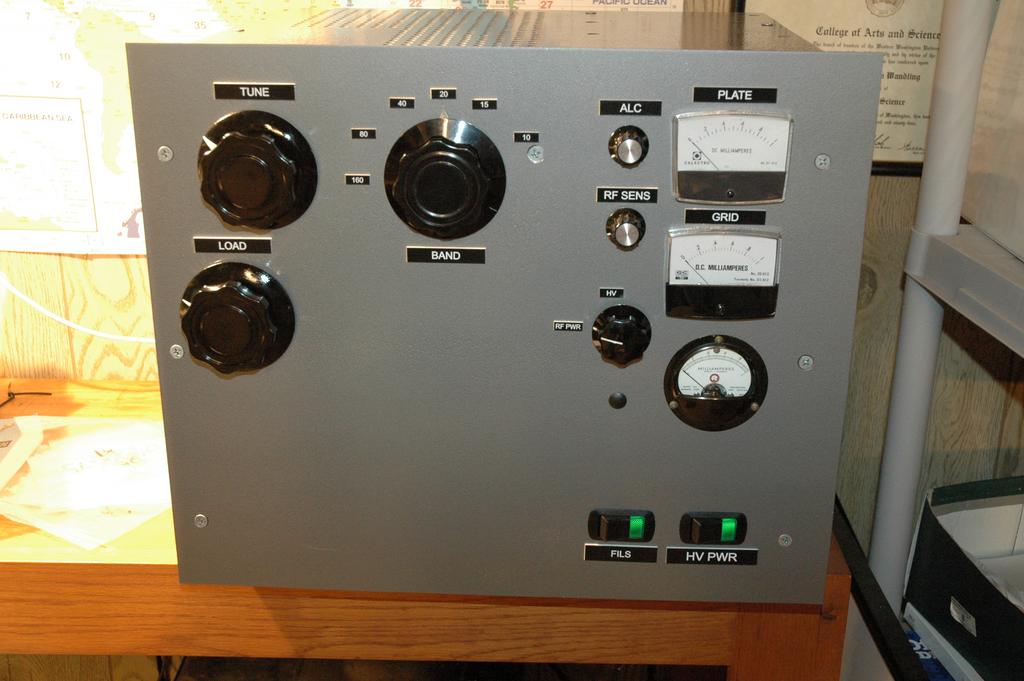
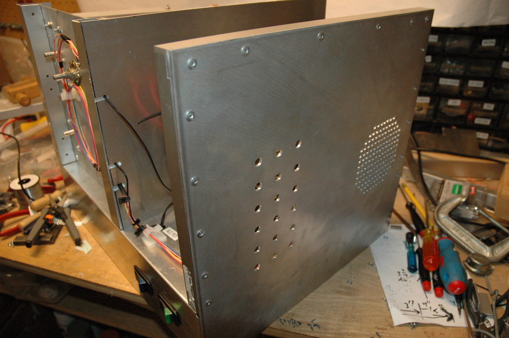
Some views of the new new panels:
Panels
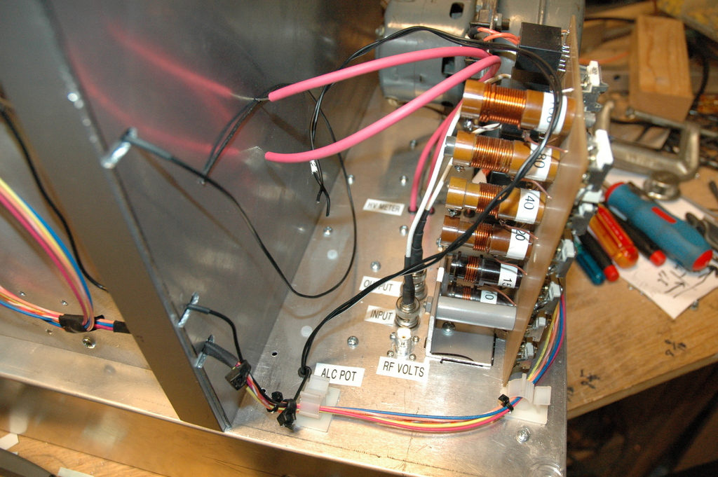
Meter wiring done:
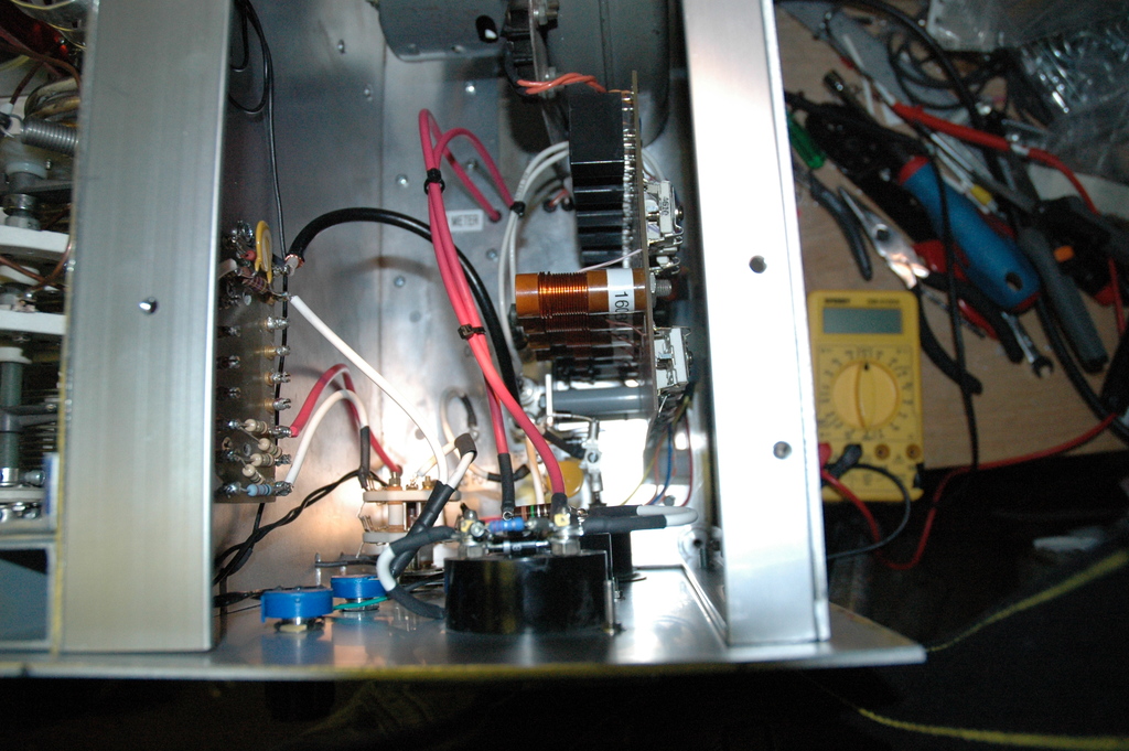
Control bay,
More control bay
The two red lines from the center towards the front panel are HV B-. The bigger black line from center towards left to board attached to side panel is RF output for the RF Voltage meter circuit (where the ceramic disc cap is).
The red+white lines to the board attached to the panel on the left are the HV B+ circuit (4 1Meg Ohm in series to the meter with a 1k ohm to ground).
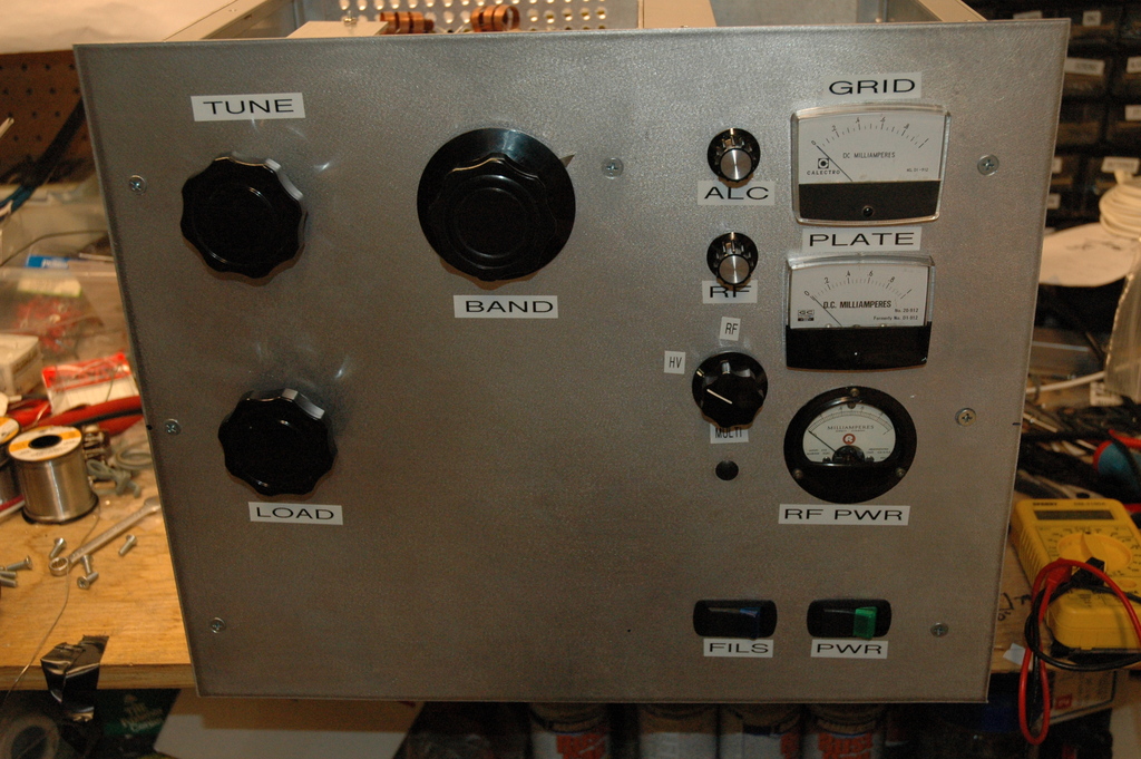
The rotator switch near the bottom left is the multi-function switch for choosing to view RF VOlts or B+ HV on the "round meter" (see last pic).
The input tuning board is seen from the top and above it is the blower.
Each meter is shunted with a resistor (except RF), two diodes, and a 1kV 0.01uF cap.
The thin black lines along the left are the ALC controls, and the small coiled up black line is a 12Vdc spare line for future lamps/controls.
The white/red wire is HV wire (15kV). The big black wire is RG-8X to carry the RF out for sampling. Connections through the chassis wall for HV, and RF are via BNC bulkhead connectors to make it easier to disconnect for service and keep airtightness.
Front panel with ALC, RF Sense, multi-switch (view HV+ or RF Volts), meters for grid & plate current. Front panel
Originally designed for 10m thru 160m, it represents a lot of work on the part of Jim to collect the parts, design the layout and prepare the power supply.
What I have here is the makings of a really good linear amp. The parts include, most of the RF tank components, the tubes, chimneys, blower, input tuning board, an outboard (and on dolly wheels!) 4kVAC power supply, and bags and bags of smaller parts to make up the control panel, band switches, loading capacitors, and more.
I took pictures of the major parts the day after receiving them and wanted to put them here to document the process for rebuilding the amplifier.
Jim gave me the manila folder full of designs, schematics and information on linear amplifiers and I will absorb as much as I can from it.
On to the pictures.
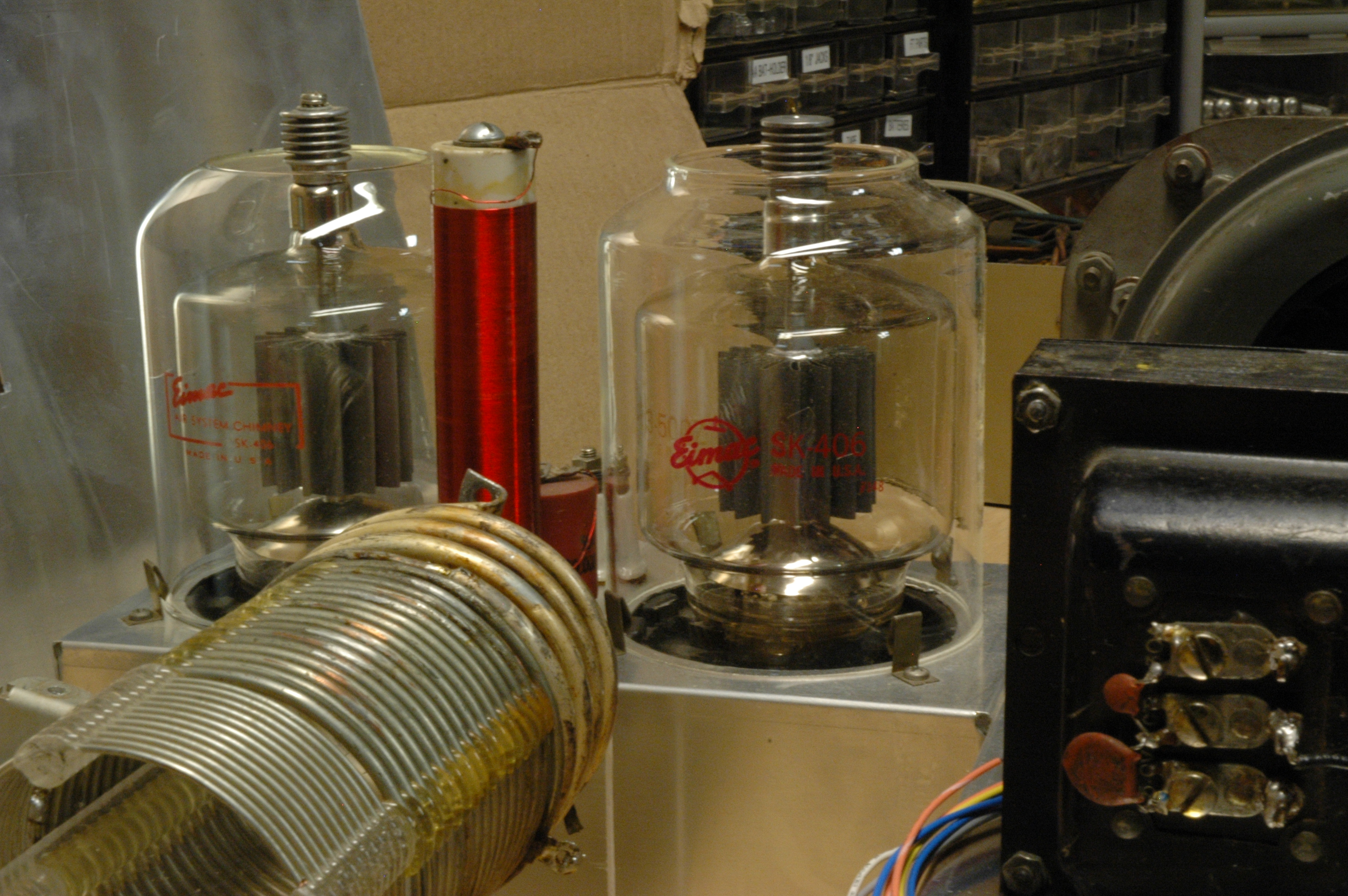
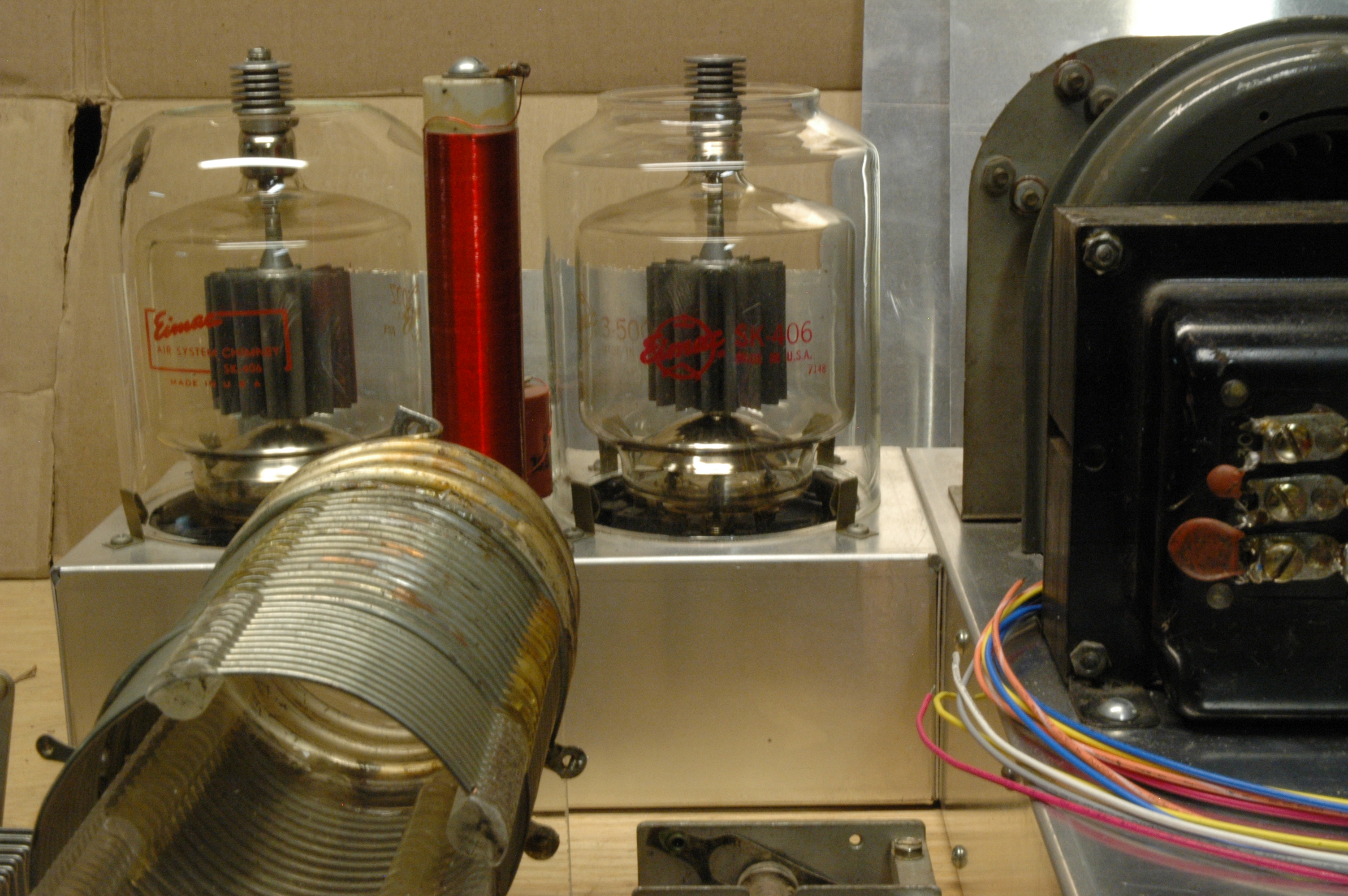
Air blower (grey manifold behind tuning board) forces air under the chassis through a formed
cavity to make the air come up around the base of the 3-500Z and through
the chimneys.
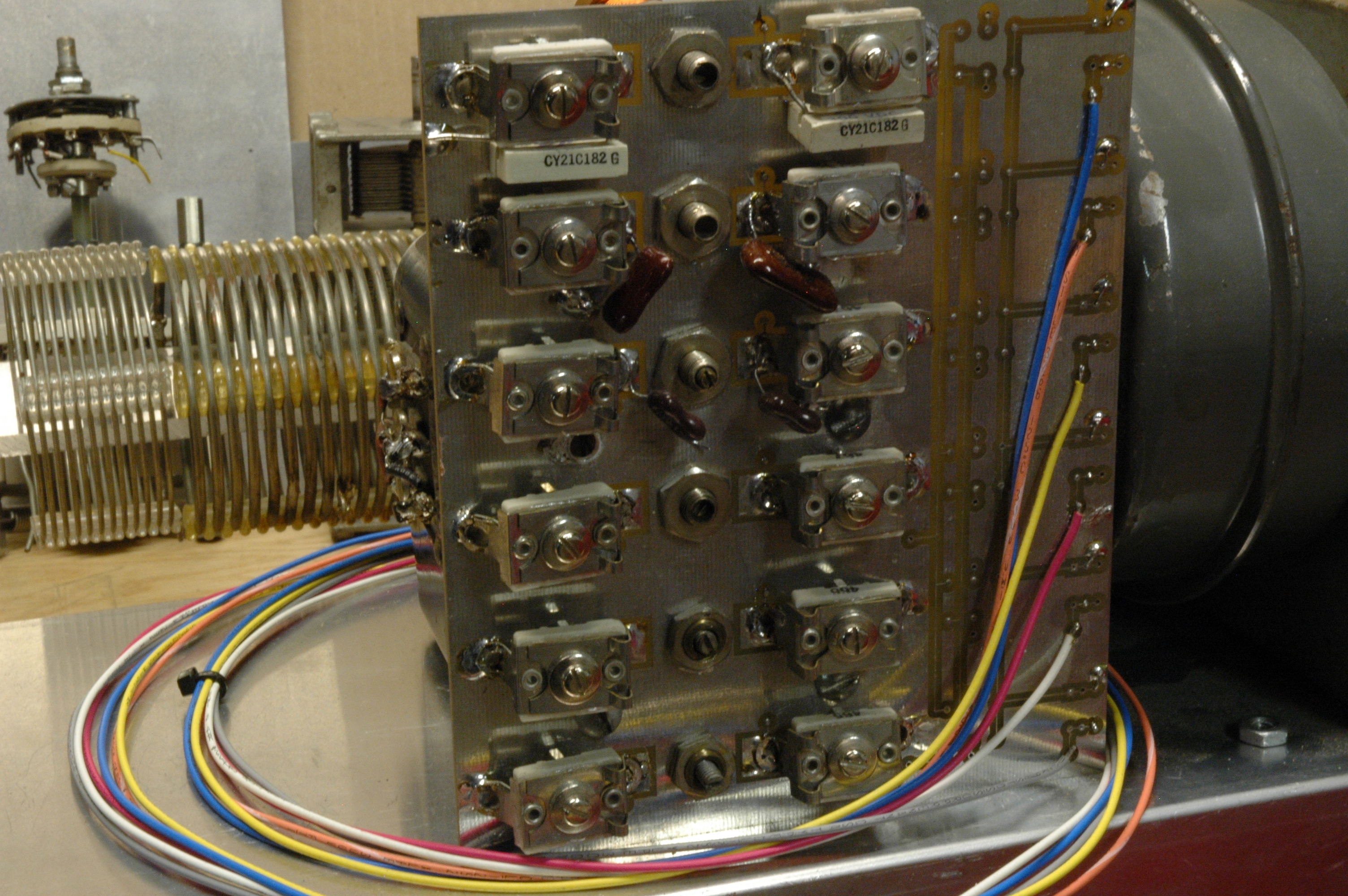
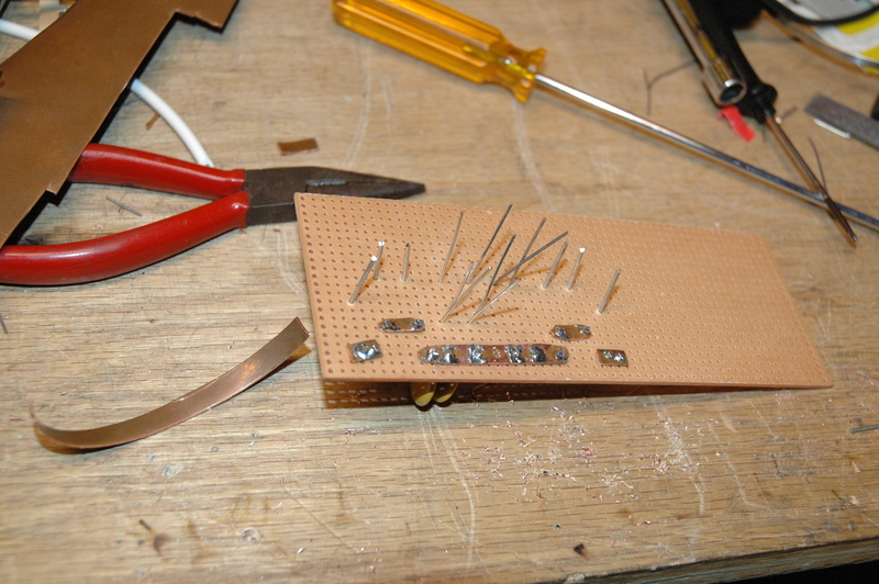
The input tuning board.
Input Tuning Schematic
The input tuning board.
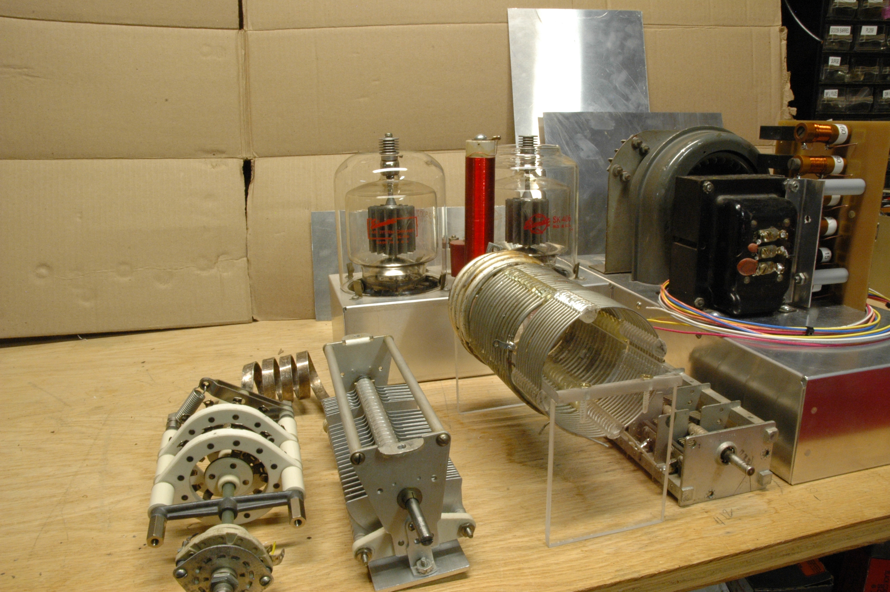
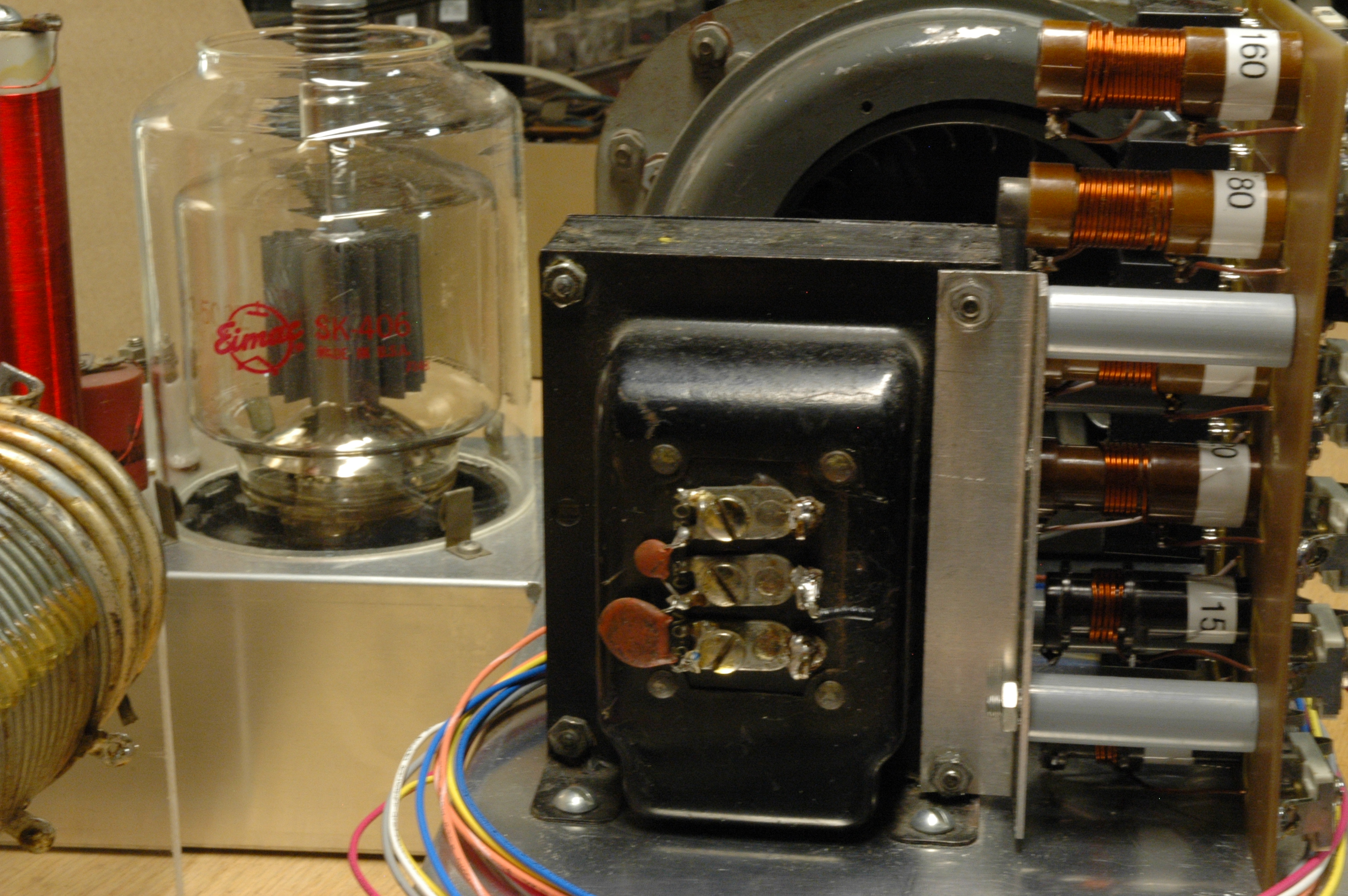
RF Tank Parts
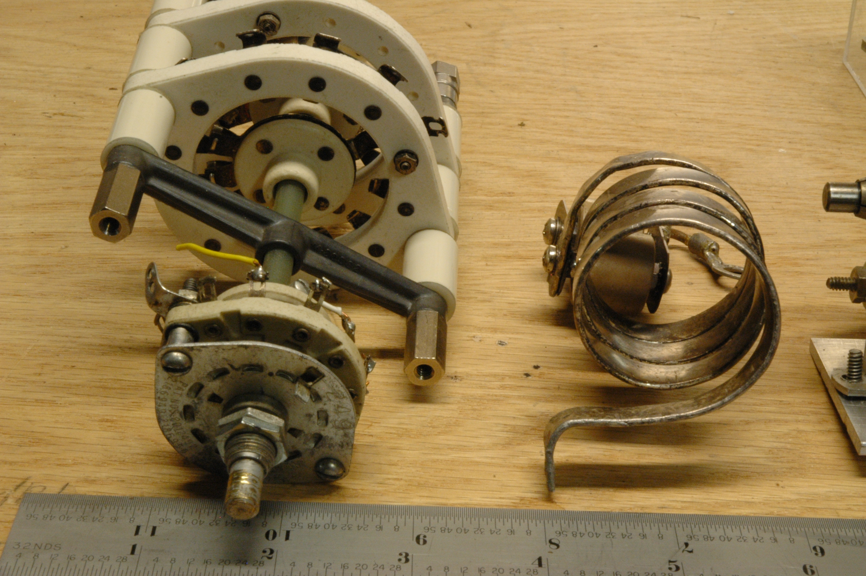
Bandswitch
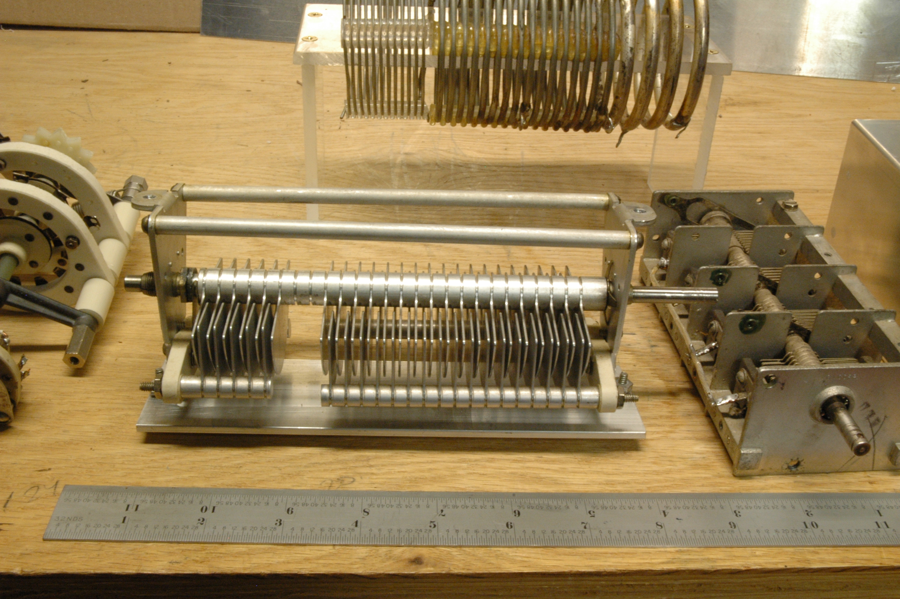
RF Tank Parts

RF Tank Parts
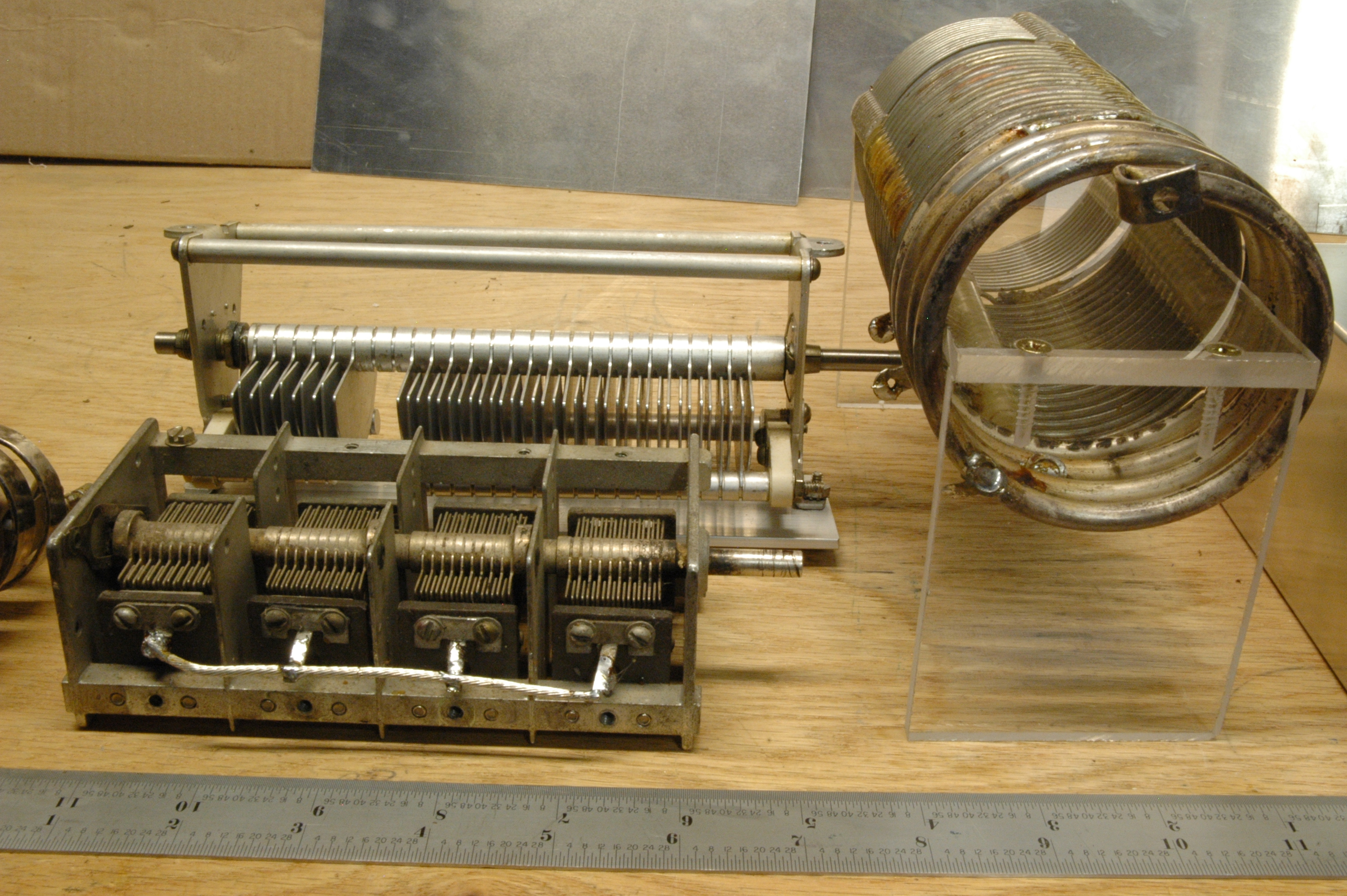
RF Tank Parts
By far the best source of parts is RF Parts.
Their service and expertise is second to none for the amatuer radio
homebrewer. If you're looking for parts for your linear amplifier project,
get their catalog. You won't be dissapointed.
For general parts and components, I use Mouser
because their website has a better search tool than Digikey. Mouser's
ordering system is very smooth and delivery options are excellent.
Locally, in the Puget Sound area, there are a few shops of varying degree
of utility:
Things to bring to the fleamarket: A shopping bag, a Digital meter,
screwdriver, pliers, and a 6" scale, and a scratch pad for taking notes.
![]()
![]()
Credits: Original Schematics and Amplifier design: K7NCG
Sources and Advice
There's nothing that wasn't easy to do on this project, but what made a
difference was getting the right parts and tools for specific elements.
Flea Markets and Building
Don't underestimate the flea-market. I purchased many tools and parts for
this amp pennies on the dollar. Meters for $2, wire, tools, ceramic
rotator switch hardware, ferrite rods, transformers, power-supplies,
coax, ceramic standoffs, and jumper-wire-up boards, copper-clad
PCB, etc... Keep a list of what you'll need so the next fleamarket you
visit you'll be prepared.