The dimensions of the sunken cavity is 10" tall, by 9.5" deep and 10" wide from the front panel side.
There's a 1" gap between the tank and the plane for the front panel.
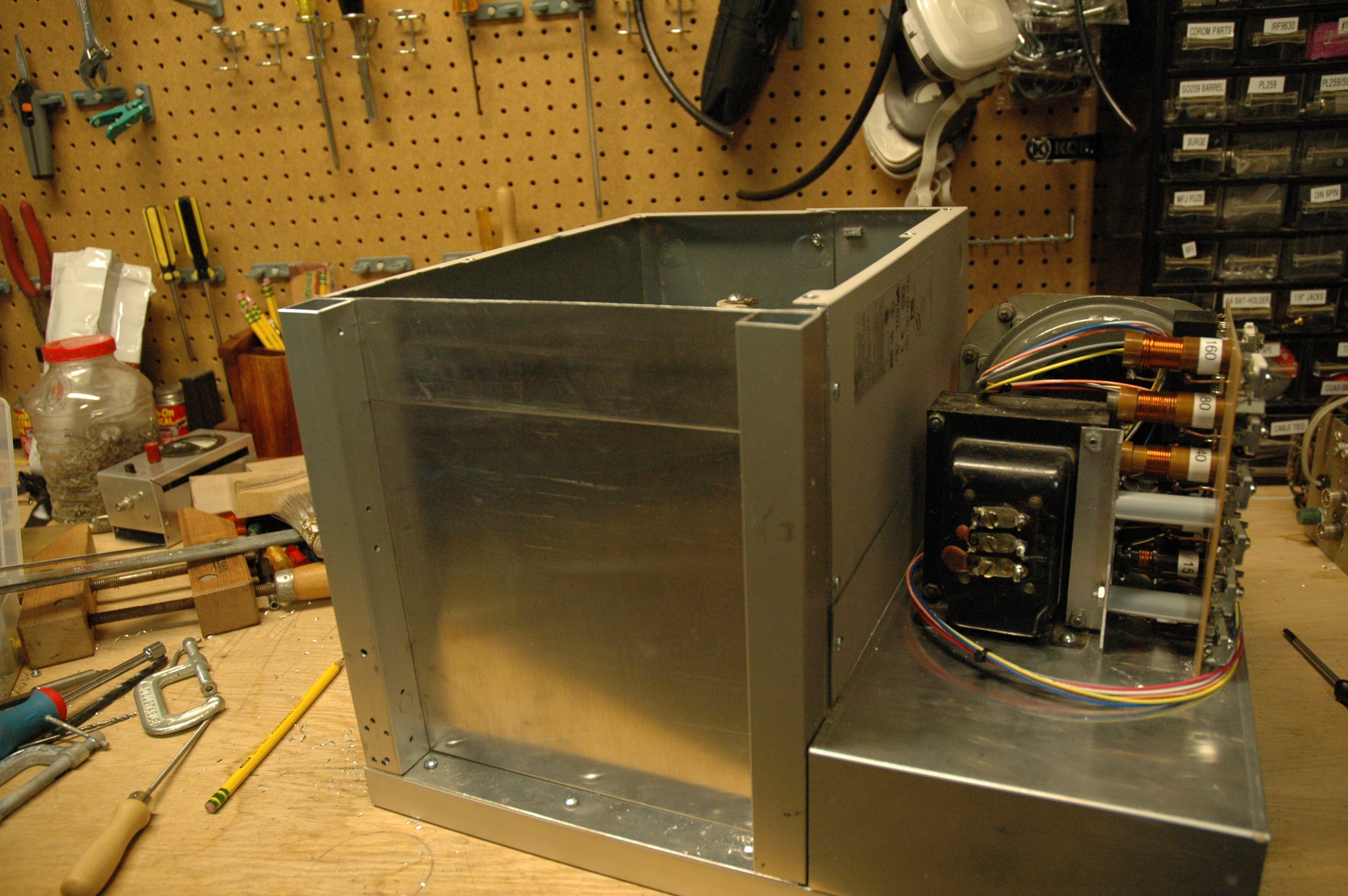
The front panel shown is 12" high and 19" wide.
The width of the chassis is 17". There's overhang on each side to allow
for the design to be rack mounted.
There may be some work to insert a spacer between the front panel and cavity
between the tank and front-panel -- it may not or may not be necessary.
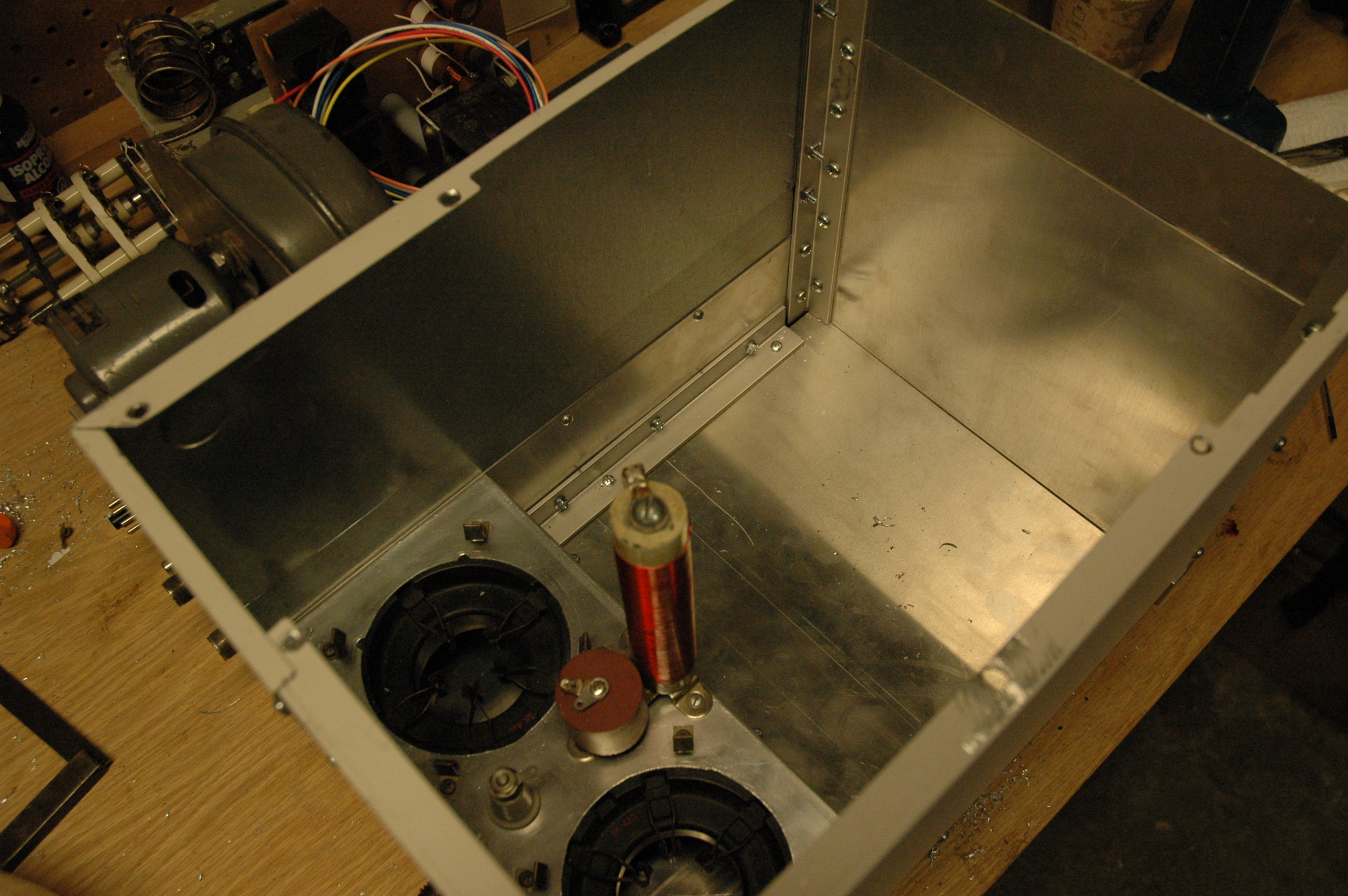
The band switch is in the center, and close to the coil. The tapped-coil
is beneath the bandswitch. The bandswitch will be mounted closer to the
wall of the tank (towards the front), but still as close as possible to the
tapped coil.
The air-variable capacitor on the left is vertically mounted (a right-
angle gear will bring the shaft to the front panel).
The fine tuning capacitor is on the right and near the bottom.
The goal is to have the capacitor drives come out at the same height
and the bandswitch come out in the center (as close as I can) and still
be close to the coil.
Bandswitch mounted. Needs to be wired into input tuning network.
The bandswitch, with the contacts cleaned with silver-cleaner:
Side View: Wired tank between bandswitch, and Tune and Load capacitors:
Top View: Wired tank between bandswitch, and Tune and Load capacitors:
The top light for Filament, and bottom for HV Cont.
The two SPST switches will go beneath the RF Volt meter. Another
set of controls will go under the ALC adjustment as needed (for fine
tuning or other functions)
The Tune and Load air-variable caps will be adjusted by the two holes
on the left vertically aligned. No knobs shown because I need to
put an extender on the shaft to bring it through the front panel.
The front panel is 1/8" aluminum cut 18" x 12". It is revision A. Just
a mock up panel. The next revision will be cut approximately the same,
but taller to stand the amp higher. There is some circuitry under
the RF Tank that needs more room than I originally thought.
The bandswitch is mounted in such a way as shown that the 10m band is about 2-oclock position and 160m is about 8 oclock position. That will change. I will remount the bandswitch so to make the 160 thru 10m spread more even so that
160 will appear about 9 o'clock and 10m about 3 o'clock.
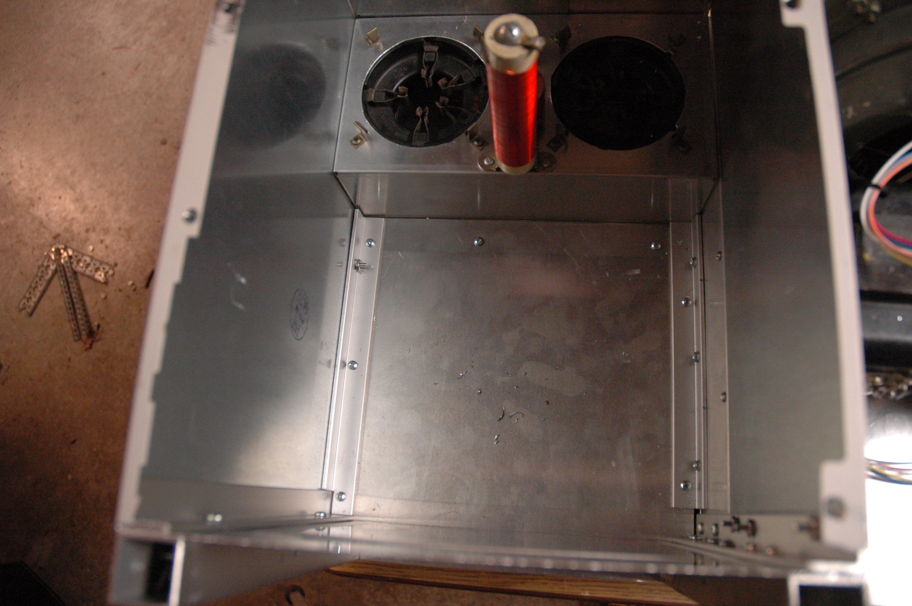
There is nothing below the bandswitch because in the RF Tank, a big coil
is sitting there!
The input circuit wiring will come into the cavity between the RF Tank
and front panel from the right side post. The meter, ALC, bias, and PTT
circuit will be installed above and below the chassis to the right of the
RF Tank.
I am debating about how to back-light the meters and how to provide
illumination for the bandswitch selection and tune/load dial. I might
use a peice of plexiglass that is etched in certain patterns/letters/numbers
on the surface to diffuse the light and create illuminated markings on
the front panel.
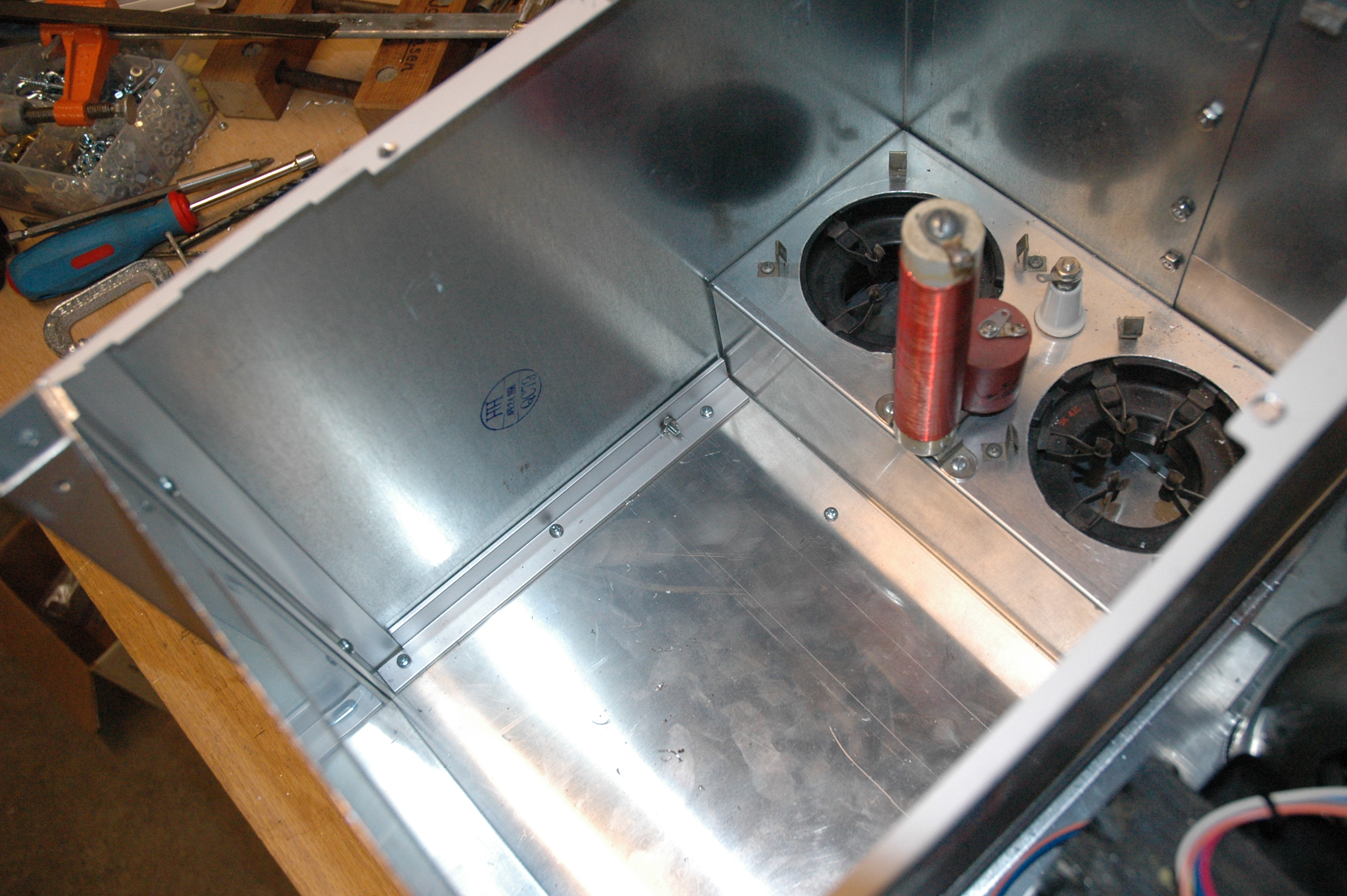
Counter clock-wise from the filament transformer: four AC chokes (-B voltage,
Filament, HV Control and Common), two terminal blocks for junctions,
12Vdc power supply, Stand-by and Power switch, Zener diode and
50W heatsink, homemade PCB with ALC circuit, 125vAC ALC power supply,
Filament Chokes.
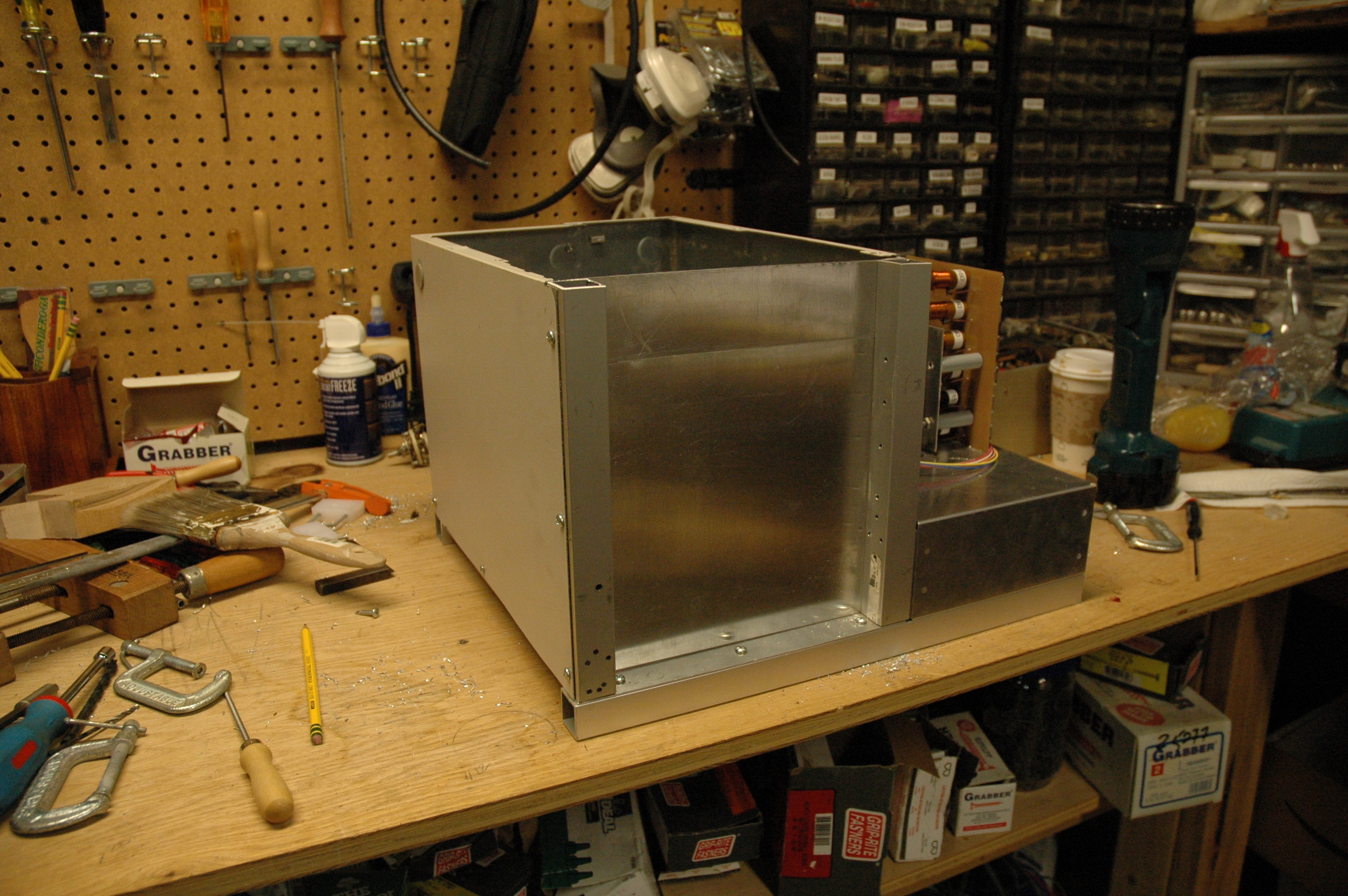
Hole above two terminal blocks is where blower fits on top. Two holes
on upper left are beneath 3-500Z (see other pictures).
Input tuning PCB and blower on right side.
Test front panel; just for fit and testing. A new panel will be made
that is taller and fits better. Metering, switches, and tune/load
dials put on for fit and testing.
Front Panel
The plexiglass sheet is approximately what I will use for the front panel.
I didn't have a thick sheet of Aluminum to use as a place holder. The
Load, Tune, Bandswitches, Meters, etc.. will be mounted on the front panel.
Coil and Cap Layout
Here, the load and tune capacitor are layed out just for sizing up placement.
They are not set in and askew. They'll be mounted good and square eventually.
Tank With some Rough In Setup
Tune, Load and Coil mounted on a temporary plexi-glass panel for placement.
Day 4 Work
Wired in the bandswitch, tune and load capacitors.
Day 5
The rough-in front panel. The meters placed are for grid and plate
current. Another (3rd) meter will go where sketched for RF Volts.
The two holes beneath the Plate meter are for ALC and RF Sens adjustment. One hole is filled with the 100k ohm ALC adjustment. The other hole on the left of that will have the 25k ohm RF Voltage Sense adjustment.
Panel from the front with the plans!
Day 6